A TPMS receiver that speaks 29-bit extended frames will not simply "work" on a controller that
was written for 11-bit identifiers — the acceptance filters, the tooling and the mapping all have
to match. Below is what actually changes, parameter by parameter, and the four questions that
decide whether the integration takes a day or a month.
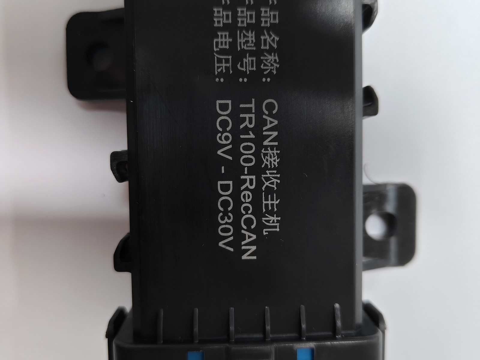
*The receiver is one node on the bus. Whether your controller sees its frames is a filter question,
not a sensor question.*
What "29-bit" changes, concretely
A CAN frame carries an identifier. Standard frames use 11 bits, extended frames 29. That
difference is not cosmetic:
- Address space. 11 bits gives 2,048 identifiers; 29 bits gives about 536 million. Only the
extended space has room for the parameter-group scheme that J1939 relies on.
- Arbitration. Identifiers also decide bus priority. With extended frames the priority lives in
the first bits of the 29-bit identifier — so two devices using different numbering schemes can
collide in ways that are hard to see on a simple trace.
- Filter configuration. This is where projects actually break. A controller configured for
standard frames will drop extended frames silently. Nothing errors, nothing logs, the data just
never arrives.
Silent drops are the expensive kind of failure, because the first place you notice is downstream,
in a dashboard that shows nothing.
The output side, in numbers
These are the receiver figures we publish, and they are the ones to put in your specification:
| Parameter | Value | Why it matters to the integrator |
|---|---|---|
| Sensors per receiver | up to 256 | One receiver covers a whole machine, including 160-wheel transporters |
| Interfaces | CAN / RS485 / PROFINET / RS232 / Modbus RTU | Interface is a part-number decision, not a software setting |
| CAN bitrate | 250 kbps, software configurable | Must match the segment; some sites run 500 kbps |
| CAN data period | 10 ms | This is the receiver-to-bus refresh, not the sensor radio interval |
| Sensor-to-receiver interval | configurable, ≤3 s | Slow by physics; do not design a control loop around it |
| Supply | 10–30 V DC | Vehicle and fixed plant both covered |
| Protection | IP68 (receiver) | Washdown and yard conditions |
Two of those rows get confused constantly: 10 ms is the bus refresh, the radio interval is
seconds. If a specification mixes them, the integrator will size buffers wrongly.
How the 29-bit identifier is structured
J1939 splits the 29 bits into fields: priority, a parameter group number (PGN) made of a page bit,
PDU format and PDU specific bytes, plus a source address. You do not need to memorise the layout
to integrate, but you do need to know that **the mapping from "tyre pressure" to a PGN is an
agreement, not a standard**. J1939 defines the container; it does not define a mandatory
tyre-pressure message that every supplier must use.
That has a practical consequence: two TPMS receivers claiming "J1939 output" can use different
PGNs, different scaling and different byte orders. "It speaks J1939" is not a specification. Ask
for the message map.
Where the mapping work lands
There are three arrangements, and the cost differs by an order of magnitude:
1. Fixed map. The receiver sends pressure and temperature in a documented layout, and your
controller decodes it. Cheapest, provided the document exists and the scaling is stated.
2. J1939 PGNs. The receiver maps its data into PGNs your platform already understands. Best
when the platform is already J1939-native; requires agreeing the PGNs in advance.
3. Customer-defined frames. You define the identifiers and the receiver is configured to emit
them. Most flexible, needs the most specification work up front.
Our own approach follows the third arrangement where the project allows it: the customer keeps the
CAN definitions, we work from the list of data points that the customer decides to expose. The
frame map and a DBC are released under NDA, which is why this article describes the structure
rather than our specific identifiers.
Four questions that decide the timeline
Ask these before the purchase order, and ask them of any supplier:
- **Does your controller accept 29-bit frames natively, and can that be changed in application
code or only through a vendor tool?** If only through a tool, that tool has to be on site.
- What does your tooling consume — a DBC, a message map, or PGN documentation? These are
different artifacts; supplying the wrong one costs a week.
- Who owns the scaling? If the receiver sends raw counts and the platform expects engineering
units, someone has to own that conversion in writing.
- What happens to a frame that arrives with one wheel missing? The layout has to say. Silent
zeros are worse than a flagged error.
Three failures we see repeatedly
The silent filter drop. Extended frames configured on a controller that only accepts standard
frames. The fix is one register, but finding it costs a day of scope time.
Two devices, one PGN. The receiver and another ECU both use a PGN that was never confirmed to
be exclusive. On a bench it works; on a machine with the second device fitted, frames overwrite
each other.
Scaling drift between bench and vehicle. The bench test decodes raw values; the platform
assumes bar and Celsius. Everything looks plausible and is wrong by a constant factor — the worst
kind of defect, because the numbers never look obviously broken.
Bench test it before it goes on the machine
The cheapest place to find an extended-frame problem is a bench with your controller, our
receiver and a CAN analyser on the same segment. Put those three things together before anything
is fitted to a vehicle, and ten minutes of tracing answers questions that cost days in the field.
What to check, in order:
- Does the analyser see the frames at all? If it does and your controller does not, the
problem is the controller's acceptance filter, not the receiver.
- Do the identifiers match the map you were sent? Compare raw identifiers, not decoded names.
A tool that silently re-bases identifiers will make a correct map look wrong.
- Does the scaling survive a round trip? Decode one frame by hand and compare against the
document. If the bench decode and the document disagree, resolve it before the vehicle work.
- What does the receiver send when a wheel is absent? Remove one sensor and watch the frame.
The documented and observed behaviour should match; if the layout has no defined absence value,
that is a specification gap worth fixing now.
Two practical notes. Keep the analyser passive while your controller is transmitting - a second
active node with a conflicting map is the most common bench trap. And log to a file rather than
reading a live scrolling view, because the interesting event is usually the one you scrolled past.
What the 10 ms figure does and does not mean
The receiver refreshes its CAN frames every 10 ms. That is the number to give an integrator who
asks how fresh the bus data is, and it is fast enough that a controller can treat it as a normal
vehicle signal.
It is not the sensor radio interval. Sensors transmit on a much slower cycle - seconds, not
milliseconds - because they are battery devices sharing a radio band. If a specification implies
that tyre pressure is measured 100 times per second, that specification is wrong, and a control
loop designed around it is designed around a number that does not exist.
Keeping those two rates separate is, in practice, the difference between a specification an
integrator can implement and one that produces arguments in week three.
How we normally start
If the machine already has a controller or a platform that expects tyre data on a bus, this line
is the fit — see the receiver range for the interface variants and
the product overview for how it sits with the rest of the system. If you are
integrating into a machine controller rather than a fleet platform, the deployed configurations on
the solutions page show what has been built for cranes, stackers and haulers.
One question, and we can answer in writing: what does your controller accept today — raw
29-bit frames, J1939 PGNs, or a fixed CAN map you define? Tell us that plus the wheel count, and
we will tell you which of the three arrangements fits and what documentation you would receive.
FAQ
- Does a 29-bit TPMS receiver work on a controller that only accepts 11-bit frames?
- Not directly. The controller must be configured for extended-frame acceptance and its filter/mask registers set to the extended-id format. Some controllers expose this only through a tool, not in application code.
- Is J1939 the same thing as 29-bit CAN?
- No. 29-bit is the frame format; J1939 is a higher-layer agreement on how the 29-bit identifier is split into PGN fields. You can have 29-bit frames that are not J1939.
- Do I need the DBC file or the message map?
- Both are useful and they answer different questions. The message map tells you what each frame carries; a DBC lets a tool decode it automatically. Ask for whichever your tooling consumes, and ask who owns the scaling.
- Can the receiver output both formats at once?
- Some configurations can present 11-bit and 29-bit output on separate channels. That is a project decision, not a default - state it before the order, not after.